CCM, a family of magnetic components dedicated to space applications and optimized for multi-output flyback converters
INTRODUCTION
In the mid 2010s, EXXELIA decided to develop a family of products capable of withstanding the harsh environments of aerospace and especially space, and complementary to our existing SESI and TT families. We decided to develop Chameleon Concept Magnetics (CCM).
The range currently consists of 5 sizes, CCM4/5/6 and CCM20/25. The maximum transferable power in the CCM25 is about 200W, depending on the operating conditions of the transformer. A CCM30 is currently under development. This would approach 350W. The internal construction of the CCMs is similar to that of the SESIs, but there are some differences. We wanted to optimise the reproducibility of the electrical characteristics. We defined sizes with many connections, to focus on multi-output applications. CCMs are more compact and higher than SESIs. Today, the raw materials used all have a thermal class of 180°C.
Figure 1 : Overview of the current CCM range
PART 1 : SPATIAL QUALIFICATION WITH ESA/CNES
The qualification of SESI concerned standard ranges of QPL differential mode chokes and common mode chokes. Over the years, we have seen more and more developments of specific, so non QPL products. In these cases, the technology used was space compatible, as the inductors were space compliant and the raw materials and manufacturing process were almost identical. However, these products did not have QPL status.
For the 5 sizes of the CCM family, we chose to do things differently in order to have a valid qualification for all types of functions, inductors and transformers. We chose to apply for and pass a Technology Know-How Approval (TKA), which has since become Technology Flow (TF).
The principle of TF is to define precisely the technology with which products will be manufactured, associate to it design rules with it, evaluate the technology and then qualify it. Once the TF is obtained, any product that meets the technology and design rules has the status of qualified and can be used without further testing. This saves money and time.
The TF consists of two successive phases whose objective is to demonstrate the reliability of the technology with respect to all the constraints that the component will have to undergo during its life. The first phase is the evaluation phase, the second is the qualification phase.
The evaluation phase is the most important one, as it is the one that must show the robustness of the technology in all stress domains. It is on the initiative of EXXELIA. The qualification, supervised by CNES and ESA, only confirms the compatibility of the technology with the space environment on a limited number of tests and components representative of the whole range of sizes.
Before starting the tests, EXXELIA defined the framework of the CCM technology, i.e. two detailed and exhaustive lists, one for the raw materials and one for the manufacturing operations. With regard to raw materials, all categories were well defined:
Magnetic circuits / cores : manufacturer(s) and material(s),
Bobbins : dimensions and materials,
Winding wires : manufacturer(s), grade of insulating enamel, thermal class, and diameters,
Solid insulators: manufacturers and materials,
Glues, resins and varnishes: manufacturer(s) and references,
Solderings and fluxes,
ESD packagings.
With regard to manufacturing, all operations from winding to packaging were also detailed. Thus, with these two lists, the framework for CCM technology is perfectly clear.
In addition to these manufacturing constraints, EXXELIA defined a quality framework including working methods, documents and a level of traceability compliant with space requirements.
For the evaluation phase, a large number of tests were planned and carried out in the following areas : thermal shocks, burn-in, life test, dielectric strength, internal component heating (Rth), shock and vibration mechanical resistance, brazing and soldering heat resistance, solderability, pin pull-out strength, marking resistance, and moisture resistance. In each area, a test procedure has been defined as well as the number of components involved. The ESCC3201 standard, which itself is based on several MIL standards, was used as a guide throughout the evaluation campaign, which took much time. Several hundred parts were manufactured, tested and even destroyed. In fact, in several areas, we pushed the components beyond their limits in order to determine the safety margins available to us. In all aspects, particularly thermal, mechanical and long-term reliability, we have found that they are sufficient for the needs of space.
This evaluation campaign was a success. It was the subject of a report [1] sent to ESA. The qualification phase then took over. It too was a success. A complementary document was created to follow the qualification evolutions of this technological family.
We now had a space-qualified technology family that allowed us to design a wide range of components for our customers' applications.
We now needed to know in detail how our components would behave in the customer's environment.
PART 2 : THERMAL, FREQUENCY AND SATURATION BEHAVIOURS
In order for our customers to choose the right component for their application, we need to provide them with a set of information on the behaviour of our components. We therefore decided to carry out three characterisation campaigns : thermal, frequency and saturation.
Thermal characterisation
Internal heating of components is becoming an increasingly important aspect, taking into account the increase in the ratio of power by weight and power by volume in equipment. EXXELIA has therefore launched several actions in this field. One of them is to improve our knowledge of the thermal behaviour of two of its standard component families, CCMs and TTs. During the qualification of CCMs, a campaign had already been carried out in this field. The results were neither sufficiently precise nor sufficiently complete to meet our needs for information and advice to customers. Ideally, mathematical models of thermal resistance in vacuum or measurements in vacuum should have been available quickly. Both of these are possible, but they are very time-consuming because the mathematical study involves the physics of fluid mechanics, and making thermal measurements in vacuum is complex. As a first step, we decided to carry out a characterisation campaign with natural convection in air, which will serve as a reference for the ongoing studies in vacuum. Conduction and radiation, which play a significant role in the calorie extraction, are indeed present in both air and vacuum.
In addition to the dependence on component characteristics, Rths vary according to several external parameters, in particular :
Ambient temperature,
Environment (carrier PCB/other, air/vacuum, horizontal/vertical layout, and so on),
Power level to be dissipated in the component, i.e. the losses,
Location of these losses, in the windings (copper), or in the magnetic circuit (iron core).
EXXELIA has already carried out this type of experimental characterisation in the 2000s for the SESI family of components. The objective of this study was to carry out the same work on the CCM and TT families. We only detail the CCM part.
The components are SMD. They are single-winding inductors. For simplicity of calculation of the losses, sources of heating, we chose to supply the inductors with direct current. The component winding resistances are between 5mΩ and 2Ω at room temperature. The excitation conditions are such that the maximum temperature rises bring the components to a temperature of about 180°C, which is the thermal class of all raw materials used in CCMs.
The temperature of the component is measured via the winding resistance measurement. The law of variation of copper conductivity with temperature is taken into account and it is assumed that the temperature gradient in the different parts of the component, moulding and magnetic circuit, is small compared to the overall rise in ambient temperature. The component is supplied for a sufficient time to reach the stabilised thermal steady state.
For each size, Rth measurements are made at six different ambient temperatures: 25, 50, 75, 100, 125 and 150°C. For each ambient temperature, we first determine the power point that brings the component to around 180°C. For the curve at 25°C ambient temperature, fifteen measurements of Rth are made at injected powers equally distributed between 0 and the maximum power determined previously. For the curves at higher ambient temperatures, the same power points are used, except those leading to maximum temperatures above 180°C. Two inductance values are characterised for each of the 5 sizes, i.e. 10 components to be tested.
All components are soldered onto a PCB similar to that used for SESI characterisation. The temperature of the PCB is measured throughout the tests to identify any increase in temperature.
A 112 liter ventilated oven was used. Care was taken to protect the components from ventilation inside a box. The box was defined that was large enough in comparison to the volume of the largest component to be characterised. It was perforated at the top and bottom to allow natural convection between the box and the ventilated airflow outside. The temperature inside the box was measured to identify any rise in its average temperature.
We are not going to detail more the development of the experimental bench here, but it was an important part of the work. In particular, we analysed in detail the study and the setting up of the box inside the oven, the monitoring of the different temperatures as well as all the metrology used, in particular the accuracy of the results. We also made comparative measurements at 22°C inside the oven and outside in order to verify that the oven had a sufficiently small influence on the results. Figure 2 below shows the synoptic of the bench.
Figure 2 : Synoptic diagram of the test bench
Figure 3 below shows an example of the curve obtained for a CCM20 6K8. The Rth values on the y-axis have been removed.
Figure 3 : Rth in air versus power dissipation curves for a CCM20 6K8
Once all the curves were obtained, several checks were made, firstly on the shape of a curve. The Rth decreases with the power dissipated and also with the ambient temperature, which seems to be consistent with the laws of thermics. We also compared the curves from one size to another. We are convinced that the curves obtained are close to the reality of the thermal behaviour of the component placed in this environment. It should be remembered that the role of the environment is fundamental. A provisional conclusion of all the actions underway in this thermal project is that a component has as many Rth as the environments in which it is placed.
As mentioned above, these curves for natural convection in air are to be considered as a reference. Characterisation in vacuum and the construction of a mathematical model of the thermal resistances of CCMs are underway. The results should be available in 2023.
Frequency characterization
It was concretely a question of drawing for each selected component an inductance curve as a function of frequency under constant excitation at room temperature
For each of the 5 sizes, 3 different inductance values are characterised. The 2 values already thermally characterised are chosen, plus one whose value is between the 2 previous ones. The inductances are measured with a device with an accuracy of between 0.5 and 2% depending on the measurement conditions. All components are soldered to the same PCB used for thermal characterisation. For new components, the same type of PCB is used.
All the components are powered under constant induction, so at constant V/F ratio. We have chosen a sine excitation voltage of 10mVrms at 10kHz. This corresponds to a voltage of 10Vrms at 10MHz, the maximum defined frequency. The corresponding induction level varies according to the iron section of the size, but is on average a few hundred µT, which corresponds to the order of magnitude with which Ferrite manufacturers, Ferroxcube for example, characterise the permeabilities of their circuits. For each component in each size, L is measured at 15 different frequencies distributed logarithmically between 10kHz and 10MHz, i.e. 5 measurement points per decade. In some cases, the component resonates before 10MHz. In this case, we limit ourselves to this resonance frequency. In other cases, when the impedance variations are important, this point distribution has been modified to better take these variations into account.
Figure 4 below shows two example results, for the CCM5 3.3µH and the CCM20 6.8µH. This is the series imaginary part of impedance Ls calculated via an impedance analyser.
Figure 4 : Series imaginary part Ls of the impedance of CCM5 3K3 and CCM20 6K8 inductors
It can be seen that the resonant frequencies are around 10MHz, which is logical since, as the inductance values are low, so are the numbers of turns and the parasitic capacitances. These inductors can therefore be used at frequencies well above 500kHz.
Saturation characterization
It was concretely a question of drawing for each selected component two inductance curves as a function of excitation current, under DC+AC current, one at 25°C ambient, the other at 125°C, since the saturation induction Bsat decreases with temperature.
The components tested and the test conditions are the same as for the frequency characterisation.
The definition of the excitation was relatively complex. We want the characterisation to be close to the real conditions of use at our customers. The components are therefore supplied with a DC+AC current. In converters, the AC component is often triangular with a small but significant ripple, for example 10% of the "full scale" DC. The measurement frequency was chosen to be 300kHz, a value that corresponds to the needs of the space market. We have defined a test set-up similar to a Buck converter in continuous mode. The choice we made was to keep the ripple and the frequency constant, whatever the DC current. The ripple was fixed at ±15% of the maximum DC current before the beginning of saturation for each component. The DC current was variable between 0 and a value leading to a 50% drop in inductance. The inductance was measured by the current rise slope. For each component tested, we checked whether the rise slope was a straight line, which shows that there is no saturation. If not, an average value was defined near the peak current value obtained. Saturation leads to two phenomena. Firstly, the appearance of harmonics which will deteriorate the EMC performance of the equipment. Secondly, as saturation increases, the drop in inductance becomes significant and the stored energy decreases. Our inductance measurement focuses on the first phenomenon with a short measurement time of the current rise, in order to well detect the beginning of saturation.
Care was also taken to ensure that the measurement times were sufficiently short and the measurements sufficiently spaced apart so that the temperature rises were negligible in order not to impact Bsat.
For each component of each size at room temperature, the no-load inductance value was first determined. Then the DC current value leading to a 50% drop in inductance was determined. It was decided to carry out fifteen measurements of L at injected DC currents not equally distributed between 0 and the maximum current determined previously, in order to correctly represent the saturation bend. For the curves at 125°C, the same reasoning was used, but with twelve measurement points in total, since saturation occurs earlier.
Figure 5 below shows an example of a curve obtained at room temperature.
Figure 6 : Inductance versus current curve at room temperature for the CCM5 M33
The drop in inductance is well defined. The curve does not have a rounded shape, but rather a break in slope. This is largely due to our choice to focus on the onset of saturation, which only appears at the end of the current rise, rather than a global saturation with a drop in stored energy, which would appear at a slightly higher current and would result in a smoother drop in inductance.
It can be seen that the maximum current before the start of saturation is a little higher than that written in the EXXELIA catalogue and internet site. This phenomenon concerns all values and sizes. Documents will be updated shortly.
PART 3 : OPTIMIZATION FOR MULTI-OUTPUT FLYBACK APPLICATIONS
The CCM family has been designed and qualified to produce both standard components, mainly inductors, and specific components, mainly transformers. In satellite equipment, the flyback converter has been widely used for a long time. It is simple and has a minimum number of components, which makes it reliable. The increase in the number of functions in the equipment has led to an increase in the number of outputs. This has led to an increasing problem often referred to as cross-regulation, but which is in fact a deviation of the voltages of some of the unregulated outputs from their theoretical value calculated during the design of the transformer and converter. EXXELIA was convinced that the transformer, especially through the choices made during the construction of the windings, is the main cause of this problem. We therefore decided to undertake a PhD thesis on this subject with our scientific partner, the G2Elab laboratory in Grenoble.
Two phases have been defined in this work :
Phase 1 magnetic / transformer : Understand the magnetic problem inside the transformer, identify a theoretical model to represent the phenomenon, find an equivalent electrical circuit of the transformer compatible with classical circuit software, and finally find one or more design rules to minimise or avoid the problem.
Phase 2 power electronics / converter : Analyse the converter to identify which components play a role in the problem, understand the interactions between these components and the transformer, find a method of analysis to calculate voltage deviations and choose a transformer/environment configuration that results in acceptable voltage deviations in the application.
In phase 1, we started with finite element simulation using FLUX software. We studied two transformers in CCM5 and CCM25 technology with 3 and 4 secondaries. We calculated the inductance matrix and then entered these values into the Psim software to calculate the output voltages. We made several observations :
The number of possible winding configurations is quickly enormous as the number of windings increases,
The problem is very sensitive to small variations of some coefficients of the inductance matrix,
The magnitude of the deviations depends on the (inhomogeneous) power distribution between the different windings,
The less powerful a winding is, the more sensitive it is to deviations.
We understood the link between the different types of windings and the voltage deviations. Then we looked for a mathematical model to represent the magnetic energy between the different windings wound in the copper window. We identified a method based on vector potential, making two simplifying assumptions: 1) only the magnetostatic behaviour is taken into account, neglecting losses and parasitic capacitances, and 2) the leakage energy coming out of the magnetic circuit, for example in front of the air gap, is neglected, i.e. only the exchanges of energies between the windings in the copper window are taken into account. The calculation of the inductance matrix was compared in several cases with those from the simulation. The results were very satisfactory. This mathematical method has been published in [2].
Next, we looked for an equivalent electrical circuit that was sufficiently accurate to take into account voltage deviations and compatible with circuit simulation softwares. After several attempts, the extended Cantilever model was chosen. An example circuit is shown in Figure 6. We calculated the values of the elements of this model on several examples and then introduced this circuit into the Psim software to calculate the output voltages on these examples. The results were again satisfactory. We had all the right variations, often overvoltages, sometimes undervoltages, and the deviation values were correct relative to the expected theoretical values. An example of voltage deviations obtained with a 4-output transformer is shown in figure 7. We also used this circuit by characterising it from experimental measurements made on an existing "flight model" quality transformer. The results were satisfactory.
Figure 6 : example of an equivalent extended Cantilever circuit for a 4-winding transformer
Figure 7 : comparison of the voltage deviations obtained on 2 low power outputs for 3 different types of windings
Today, we have a good understanding of the impact of the choices made at the time of the construction of the windings on the voltage deviations. We have understood that the leakage chokes between the secondaries have a major impact on the deviations. We were able to identify a link between winding order and geometry, and voltage deviations. A simple design rule that we believe will avoid the worst cases of deviations has been developed. The whole approach has been published in [3].
We started phase 2 a few months ago. In this phase we are working in two directions: 1 the analysis of the influence of several components of the converter on the deviations, and 2 the search for an analytical method to calculate the output voltages in order to avoid having to use a circuit simulation software. We have already identified some faults in some components that have an influence on the deviations. We would like to go further, but we are faced with a delicate situation: depending on the application and the customer, the number and type of components used varies greatly. With regard to the method of calculating voltages, we are on a promising way.
As a summary, we have understood how the transformer influences voltage deviations and we are able to avoid the worst cases by choosing suitable winding processes. The final objective initially defined was to convince our customers that the linear regulators they often add on low power unregulated outputs are no longer necessary. This would lead to a reduction in cost, weight and volume, and an increase in the reliability of the converters. I think we are able to achieve this goal at least partially.
CONCLUSION
Initially, the CCM technology was created with two objectives in mind:
To complete our range of space components with higher and smaller footprint components at constant power
To have a technology family with casings in order to facilitate winding (time and cost reduction) and to improve the reproducibility of transformer characteristics, leakage inductances and resistances in particular.Initialement, CCM technology was created with two goals:
To complete our range of space components with higher and smaller footprint components at constant power,
To have a technology family to facilitate winding (time and cost reduction) and to improve the reproducibility of transformer characteristics, leakage inductances and resistances in particular.
The CNES/ESA ASF/TF qualification was a success and showed that even the heaviest CCM25 (45g), which can accept up to 200W, can withstand accelerations/shocks up to 2000g under certain conditions. The technology family allows for all kinds of standard or specific functions and products for all types of projects, full space and new space.
We now have a complete set of information on the thermal behaviour of all our components, and in frequency and current saturation for our standard inductors. All this information allows us to choose, together with the customer and for each application, the lightest/smallest product capable of transferring the required power level.
Finally, for multi-output Flyback converters, we have an analysis method that allows us to avoid the worst cases of voltage deviations (cross regulation) by choosing suitable winding processes.
Exxelia is continuously proposing more through new technologies and design tools to offer their customers better solutions.
CCM technology is well adapted for space … and we continue to improve it.
See the slide
Autor : Bruno COGITORE – Jean PIERRE
Magnetic Expert / Innovation – Space product Manager • Exxelia Magnetics
REFERENCES
[1] G. Maigron, J. Pierre, « Agrément de Savoir-Faire : phase d’évaluation », EXXELIA, 2014
[2] D. Motte-Michellon, B. Cogitore, B. Ramdane, Y. Lembeye, “Application of a multi-winding magnetic component characterization method to optimize cross-regulation performances in DCM Flyback converters”, EPE ECCE 2022 proceedings, September 2022
[3] D. Motte-Michellon1,2, B. Cogitore1, Y. Lembeye2, B. Ramdane2, “A study on the influence of the transformer on cross-regulation in DCM multi-output flybacks”, 1 EXXELIA, France 2 Univ. Grenoble Alpes, CNRS, Grenoble INP, G2Elab, F-38000 Grenoble, France, PCIM 2022 proceedings, May 2022
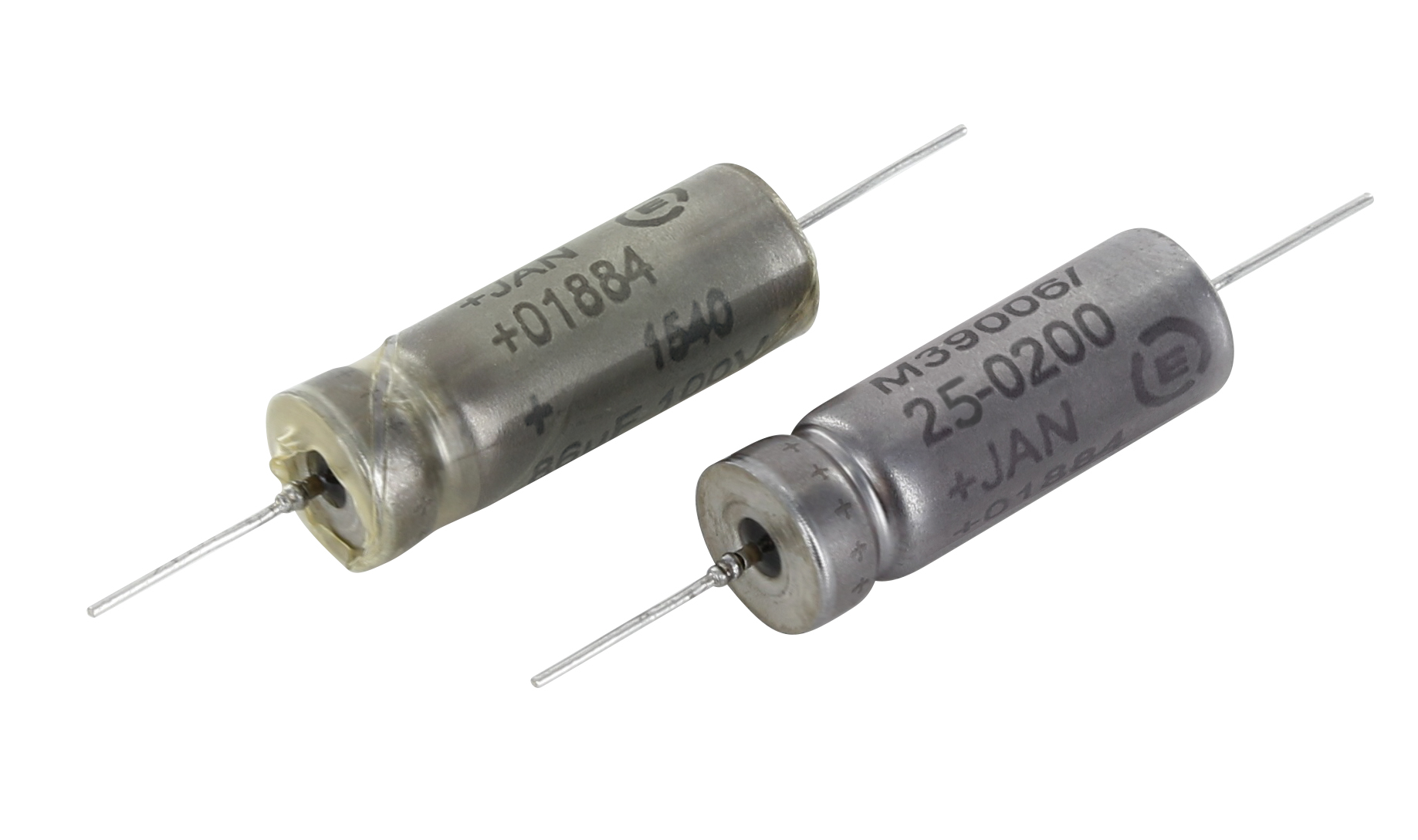 The recently introduced ranges of MIL-qualified tantalum capacitors will be showcased on the company booth (B13). MIL 39006/22 and MIL 39006/25 respectively equivalent to CLR79 and CLR81 types feature hermetically sealed cylindrical tantalum cases and axial leads are available in T1, T2 T3 and T4 cases with extended capacitance and voltage ratings. MIL 39006/22 is qualified for voltages from 6V to 125V and provides from 1200µF @ 6V to 56 µF @ 125V. MIL 39006/25 is qualified for voltages from 25V to 125V and delivers from 680µF @ 25V to 82 µF @ 125V. Both ranges combine high energy density with a large operating temperature range of -55°C - +125°C and H vibrations and shocks resistance.
 Alsic 20G is a range of radial leaded aluminum electrolytic capacitors for typical use in military and aerospace high frequency switch-mode power supplies requiring advanced performance under all operating conditions. Alsic 20G operational rated life is 8,000 hours at rated voltage and 105°C, and provides from 330µF @ 500V to 80 000μF @16V. The range features ruggedized design with insulating aluminum case and tin coated leads. With capacitance stability at high temperature, low inductance and impedance, competitive ESR and high ripple current, these capacitors are perfectly adapted for mission-critical applications.
 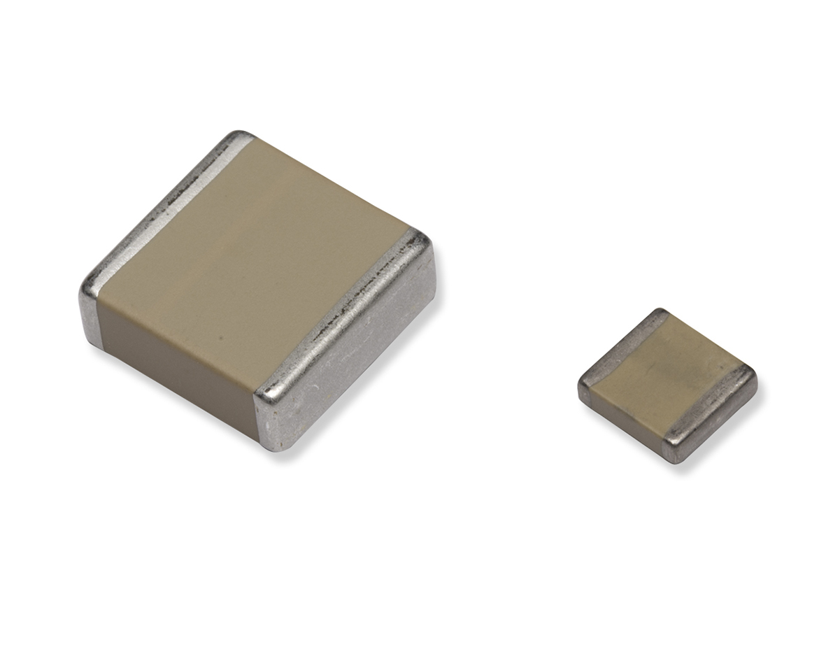 Under working voltage, C48X dielectric provides equivalent capacitance values to an X7R material with the advantage of a very low dissipation factor (less than 5.10-4). It can also withstand very high dV/dt, up to 10kV/µs which makes it perfect for pulse and charge/discharge applications for firing units. Exxelia’s C48X capacitors, available from 200V to 5kV with EIA sizes from 1812 to 16080, are ideally suited for power applications where heat dissipation may be detrimental to performances and reliability, such as 400Hz Aircraft, Ignition systems, and Space, or as Precision/filtering capacitance in thermally challenged environment for AC or DC voltage.